
|
| |||
|
|
|||
|
Current distribution calculations Antenna design and simulations Current distributions on metallic plates Inverse scattering simulations Experimental inverse scattering
|
Sinuous antenna design and simulationsSinous antennas have the following characteristics:
These sinuous antennas are used in electronic countermeasures,
radio astronomy, and remote sensing. Figure 1 shows the discretization
pattern of one of these antennas.
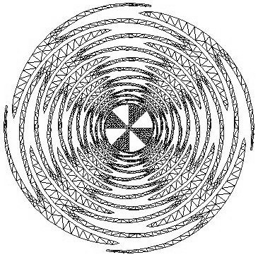 Figure 1: Sinous antenna
The design on Figure 1 was analyzed using the method of moments
to predict its performance.The SWR of the input impedance is plotted
below in Figure 2 referenced to both 50 and 140 Ohms, the
mean input impedance of the antenna.
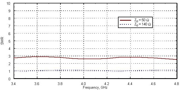 Figure 2: SWR of the input impedance referenced to both 50 and 140 Ohms
Figures 3 and 4 show the half-power beamwidths (HPBW) for the sinuous
antenna excited in the left-hand sense. Figure 3 is a cut in the phi = 0deg
plane, and Figure 4 is a cut in the phi = 45deg plane.
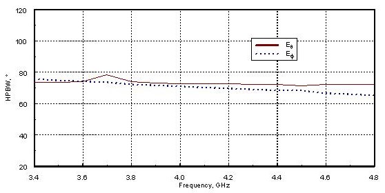 Figure 3: HPBW in the phi = 0deg plane (left-hand excitation) 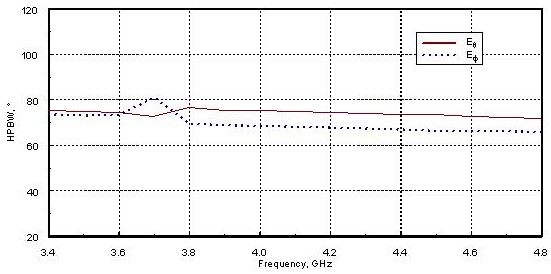 Figure 4: HPBW in the phi = 45deg plane (left-hand excitation)
Figures 5 and 6 show the same HPBW data for right-hand excitation.
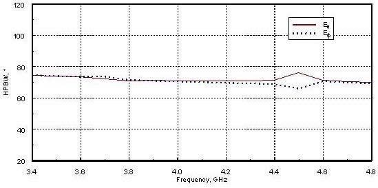 Figure 5: HPBW in the phi = 0deg plane (right-hand excitation) 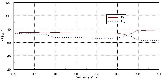 Figure 6: HPBW in the phi = 45deg plane (right-hand excitation)
Finally, Figures 7 and 8 show the surface current directed tangentially
along an arm centerline at 4 GHz.
The magnitude and phase are plotted for left- (Figure 7) and right-hand
(Figure 8) excitation. The graph abscissa denotes arc length along the arm.
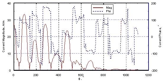 Figure 7: Tangential surface current magnitude and phase (left-hand excitation) 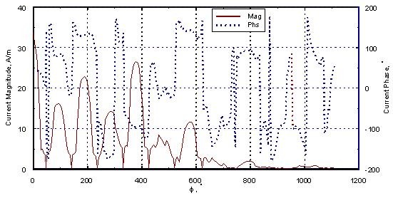 Figure 8: Tangential surface current magnitude and phase (right-hand excitation) The above work is a collaboration between Jim Bowen, Prof. Paul Mayes, and Prof. Weng Cho Chew. Please send suggestions, comments, and inquiries to: jbowen@.uiuc.edu.
|