
|
| |||
|
|
|||
|
Current distribution calculations Antenna design and simulations Current distributions on metallic plates Inverse scattering simulations Experimental inverse scattering
|
1. Fast Illinois Solver Code (FISC)The fast Illinois solver code (FISC) is a collaborative effort between the Center for Computational Electromagnetics and DEMACO to put together and industrial strength code that can solve for the radiation and scattering of electromagnetic field by and in the vicinity of complex structures. At this point, it can calculate for the scattering solution (RCS) from complex targets like aircraft, tanks, cars, etc. It uses a multilevel fast multipole algorithm (MLFMA) developed at the University of Illinois. The problem is formulated using the method of moments (MoM), where the RWG ( Raw, Wilton, and Glisson) basis functions are used. The resultant matrix equation is solved iteratively by the conjugate gradient (CG) method. The multilevel fast multipole algorithm (MLFMA) is used to speed up the matrix-vector multiplication in CG. Both complexities for the CPU time per iteration and memory requirements are of O(N log N), where N is the number of unknowns. A 2.4 million unknown problem can therefore be solved in a few hours on the SGI CRAY Origin 2000 at NCSA of the University of Illinois at Urbana-Champaign. Ordering information about the code can be found from DEMACO.
Complexity of FISC
To test the complexity of this algorithm, the electromagnetic scattering from a conducting sphere si computed
using the combined field integral equations (CFIE) on SGI Power Challenge
(single processor, 2GB of memory).
The diameter of the sphere varies from 1.5 wavelength to 24 wavelength.
The number of unknowns (N) ranges from 2,352 to 602,112, while the number
of levels in MLFMA is from 3 to 7.
The CPU time per iteration is close to 8.5x10⁻⁵ N log N and the memory
requirement is close to 2.7x10⁻³ N. 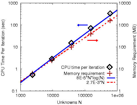 CPU time and memory requirement as a function of N
Solving Large and Complex Structures on Supercomputers
The first simulation example is the computation of the current distribution on the
VFY218 plane at 2 GHz. The plane wave is incident 30 degree from the
nose, and is vertically polarized. AT 3 GHz, the VFY218 with inlet sealed is
155 wavelength long, and is refined to 2,032,518 unknowns. The problem can
be solved on Origin 2000 with 8 processors, 6.6 GB of memory, and 13 hours of CPU time.
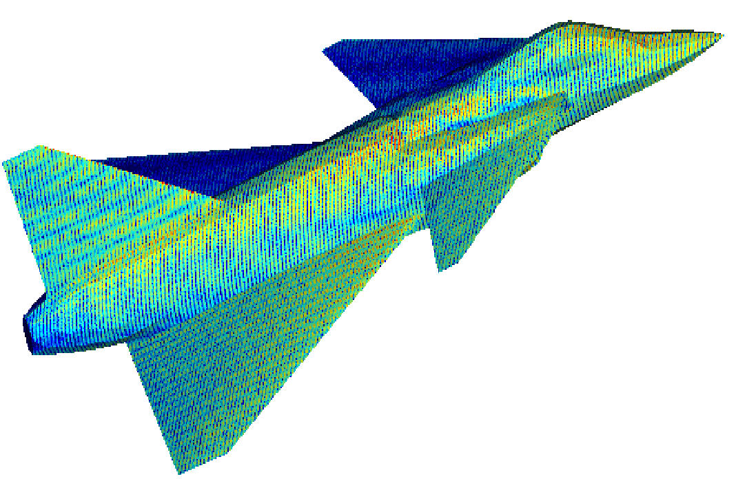 Current distribution on the VFY218 at 2 GHz.
The largest object that has been tested is a conducting sphere of 48 wavelength
diameter at 7.2 GHz (2,408,448 unknowns, eight-level MLFMA).
A total of 8 processors and 5GB of memory are used in an
Origin 2000 at NCSA, University of Illinois.
The problem takes 5 hours of CPU time to complete the
computation. The current version of FISC is parallelized for SGI CRAY shared
memory machines without changing the data structure.
Our result show good agreement with the Mie-Series solution.
The following Figure presents the Bistatic RCS computations for such a sphere.
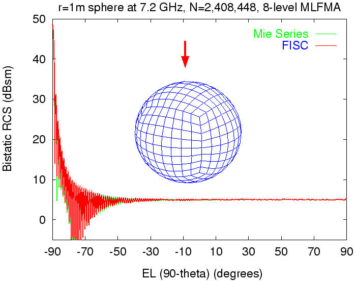 Bistatic RCS of a 1-meter sphere
Capability of handling various kinds of boundary conditions
In the following example, a 1983 Chevrolet Camaro has been modeled.
Most parts are modeled as PEC while the window glasses are modeled
as thin dielectric sheets (TDS) and the tires are modeled with an IBC.
The geometry is available in VRML
(Virtual Reality Modeling Language) format.
The incident field is generated
by a Hertzain dipole shown in the following Figure. 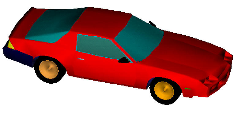 1983 Chevrolet Camaro 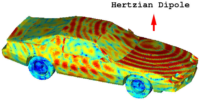 Current distribution on the 1983 Camaro at 1GHz
The above work is a collaboration between Dr. Jiming Song, Dr. Cai-cheng Lu,
Prof. Weng Cho Chew and
Dr. Shung-wu Lee. Major funding comes from DOD MURI Program. Please send suggestions,
comments, and inquiries to:
song@sunchew.ece.uiuc.edu.
2. Mixed Surface-Wire-Junction Multilevel Fast Multipole Algorithm
The multilevel fast multipole algorithm (MLFMA) has been
successfully applied to electromagnetic scattering problems of large
complex objects. By adding wire and surface-wire junction basis
functions into the existing algorithm, radiation problems of complex
surfaces and wire interconnections can be solved within the complexity of
O(N log N), where N is the number of unknowns. This extension has
several new applications, such as analysis of automobile
antennas, aircraft antennas, and electromagnetic compatibility of
desktop computers. The comparisons between MLFMA and
the method of moments (MoM) show that MLFMA uses less simulation time and
memory without losing numerical accuracy. Thus, analysis of
antennas within a complex environment can be realized on a small
computer. The following results are computed by the combination of the Fast
Illinois Solver Code (FISC) and SWJ3D
(a general-purposed three dimensional moment method code for surfaces,
wires and junctions).
Monopole antenna attached to a metallic plate
These first results test the wire and surface-wire junction basis
functions of the new algorithm.
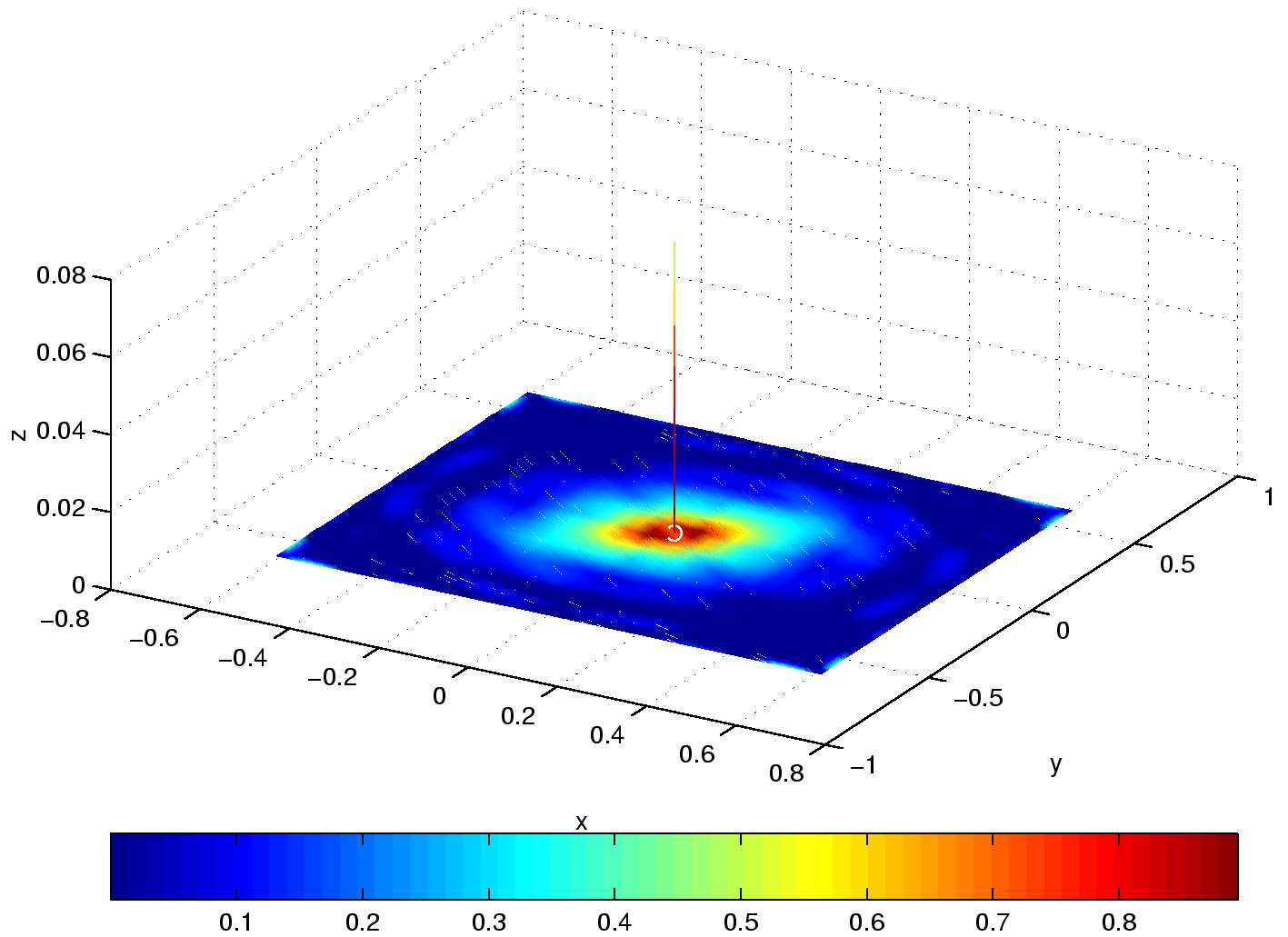
Normalized current distribution 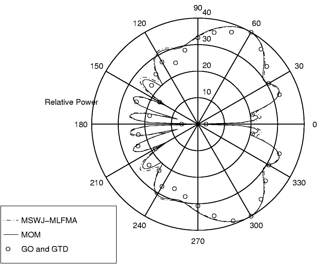
RCS
Monopole antenna attached to a car
The mesh has 2,452 unknowns. The method of moments takes 33 minutes
of CPU time and 55MB of memory on a Dec Alpha personal workstation.
With two-level fast multipole method, we just need 3.4 minutes of CPU
time and 46MB of memory. A delta voltage source is put on the junction
between the monopole antenna and the trunk. With isotropic radiation
pattern in the horizontal plane, the antenna can receive uniformly from
every direction.
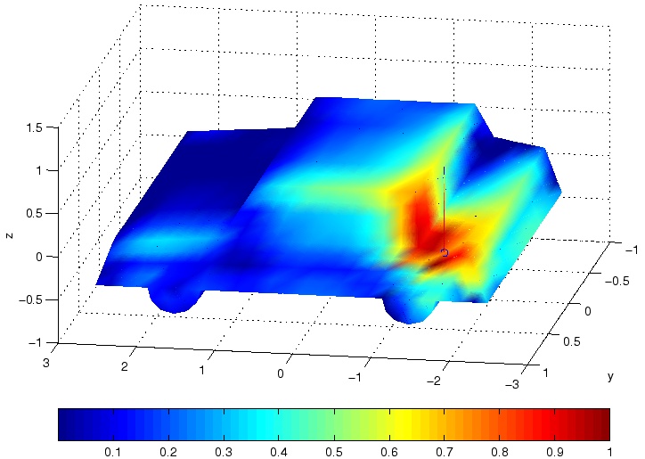
Normalized current distribution at 88 MHz (FM radio band) 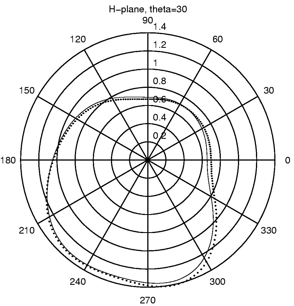
RCS at 88 MHz (FM radio band)
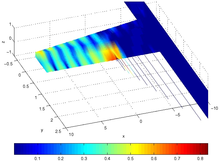
Monopole array attached to a wing
The mesh has 1,290
unknowns. With the method of moments, we need 332 sec. of CPU time and
128MB of memory on a DEC Alpha personal workstation. With two-level fast
multipole method, we only need 54 sec. of CPU time and 21.5MB of memory.
A delta voltage source is put at the junction between the shortest wire and
the wing. Most of the energy is absorbed by the fourth shortest wire due to
the resonance. The rest of the radiation is reflected from the fuselage. Thus
the current pattern is like a standing wave at the left side of the source.
The radiation pattern has two main beams radiating 30 degress upward and downward
from the wing.
Normalized current distribution at 88 MHz (FM radio band) 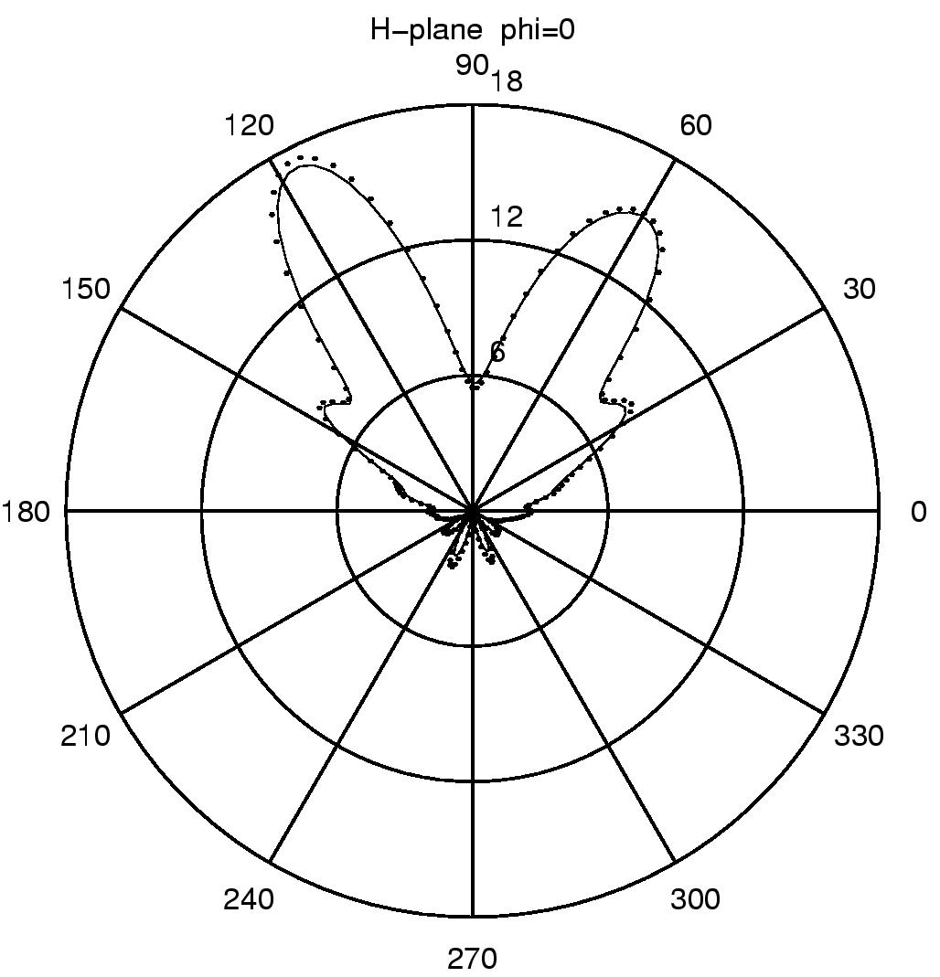
Normalized current distribution at 90 MHz (VHF band)
EMC analysis of a desktop computer
The following Figures show the triangular-patch mesh used to model the boards
and the case of the desktop computer.
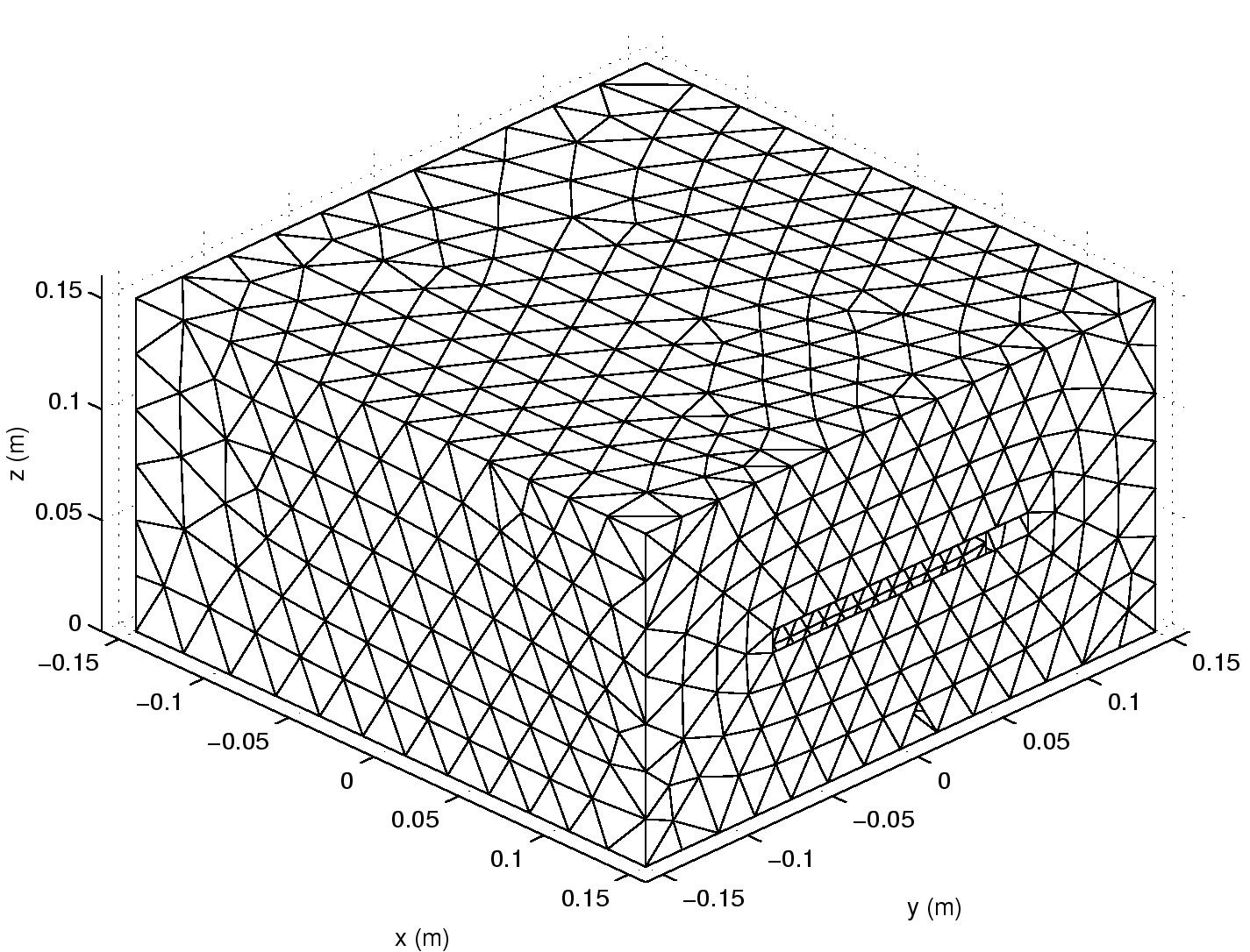
Chassis discretization - 3D Front View 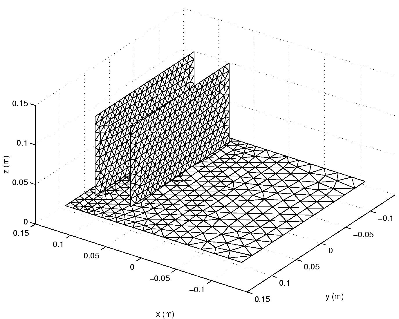
Motherboard and daughter cards discretization - 3D Back View 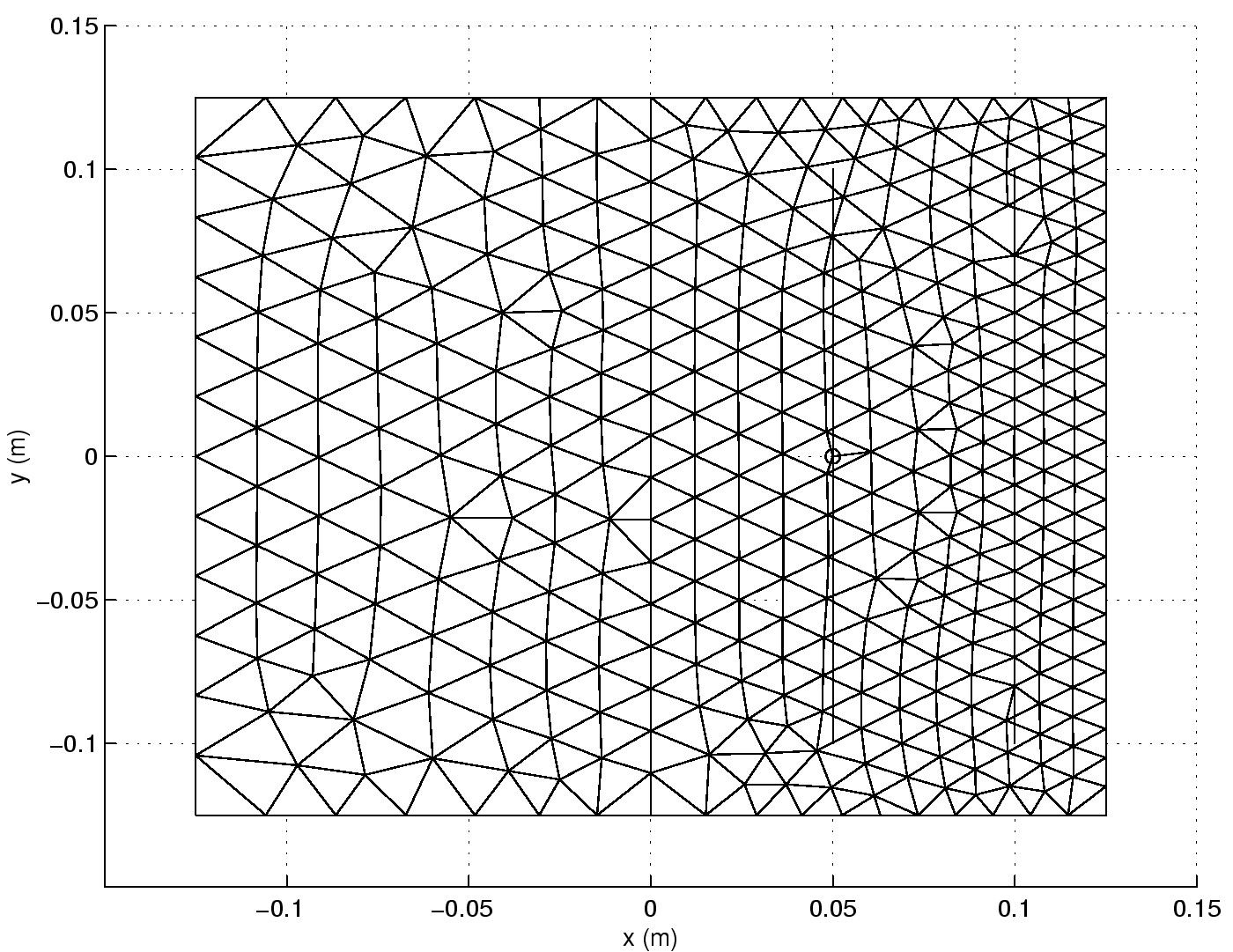
Motherboard discretization - Top View
The internal and external views for two structure with respectively 8 and 16 ground
pins between the shielding card and the motherboard are shown on the following
four Figures.
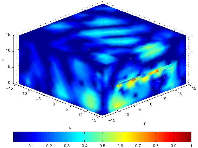
External view of the normalized current distribution with 8 ground pins 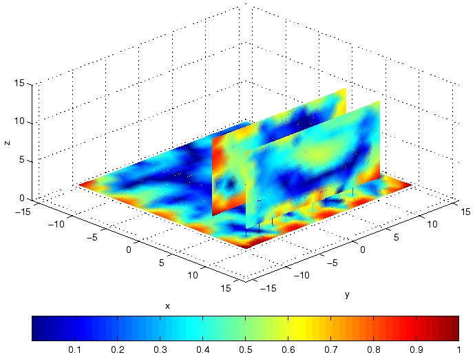
Internal view of the normalized current distribution with 8 ground pins 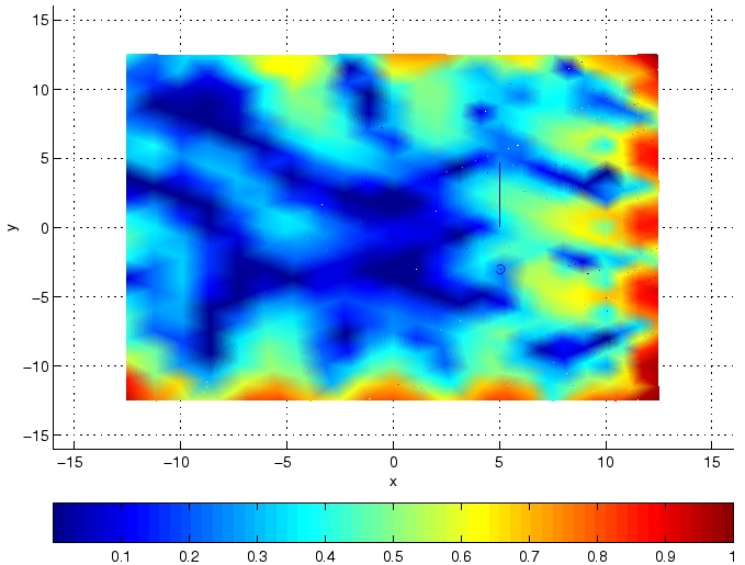
Top internal view of the normalized current distribution with 8 ground pins 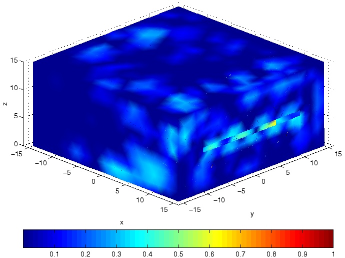
External view of the normalized current distribution with 16 ground pins 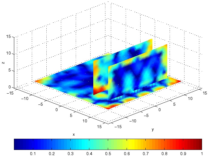
Internal view of the normalized current distribution with 16 ground pins 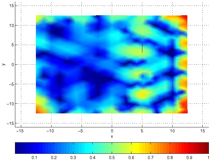
Top internal view of the normalized current distribution with 16 ground pins The delta voltage source (2 GHz) is located on a wire which connects the source card and the motherboard. By adding a shielding card with ground pins, we can effectively reduce the electromagnetic emission from the slot on the chassis. The periodic current distribution on the motherboard illustrates the resonance of the chassis.
The following two Figures show the radiation patterns of the desktop computer when
the internal voltage source is on.
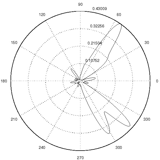
Radiation patterns with 8 ground pins 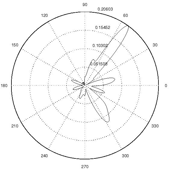
Radiation patterns with 16 ground pins
The energy radiated from the 16-pin structure is twice as much as the
energy radiated from the 8-pin structure. Thus, it appears that a better shielding
effect can be achieved with more ground pins, and more particularly at specific
frequency values, as it is shown on the last Figure.
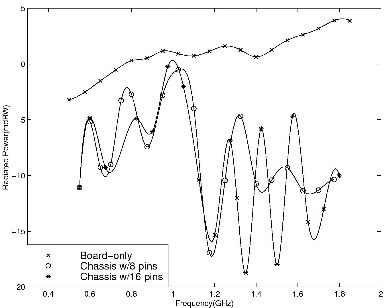
Radiated power for different configurations as a function of frequency. The above work is a collaboration of Hsueh-yung Chao, Prof. Weng Cho Chew, Prof. Eric Michielssen and Dr. Jiming Song. Please send suggestions, comments, and inquiries to: chao@sunchew.ece.uiuc.edu.
|